Version : 1.2
Author  : H.Wichmann
Date    : 04.09.2026
License : CC BY 4.0
This document provides a detailed methodological description of the procedures implemented in the Double Star Calculator [1]. It is intended to serve as a technical reference for users of the Double Star Calculator. The current version of this document is located at [2].
The Double Star Calculator derives a comprehensive set of astrometric and kinematic quantities for double star systems, including angular and spatial separations, position angles, proper motion vectors, distance estimates, tangential and spatial velocities, and derived physical parameters such as absolute magnitudes, luminosities, and mass estimates. All computations are based on established geometrical relations, classical error propagation, and standard astronomical conventions. The mathematical formulations underlying each calculation are documented to ensure transparency, reproducibility, and independent verification of the results.
This section describes the core astrometric and kinematic computations performed for stars and double star systems. These calculations form the basis of the physical interpretation and are directly used in the analyses.
For the uncertainty estimation, the following conditions apply:
This section describes the mathematical formulation used to compute the angular separation (ρ) between two stellar components (A and B) based on Gaia astrometric data.
To calculate the angular separation ρ between two celestial objects based on their Gaia DR3 equatorial coordinates (αA, δA) and (αB, δB), the Haversine Formula is used. This method is numerically superior to the Spherical Law of Cosines for small angular distances, as it avoids precision loss when the cosine of a small angle approaches. The calculation is performed in radians using the following steps:
The final angular separation is derived using the atan2(y, x) function. The atan2 implementation is preferred because it is better conditioned for all angles and avoids potential domain errors due to floating-point rounding.
The uncertainty of the separation was derived using first-order Gaussian error propagation, assuming uncorrelated uncertainties in right ascension and declination:
This function computes the position angle θ of a double star measured from North towards East (0°–360°), based on Gaia DR3 coordinates of the two components.
The position angle θ is calculated using the arctangent of the differential coordinates, where atan2(y, x) denotes the quadrant-correct two-argument arctangent, ensuring the correct quadrant of the position angle.
The resulting angle is converted to degrees and shifted to the range 0°–360°.
The uncertainty σθ is calculated using first-order Gaussian error propagation, based on the partial derivatives of atan2:
Where xi ∈ {αA, δA, αB, δB}
The Double Star Calculator extrapolates the position of two stars, as well as their separation and position angle, from the Gaia DR3 reference epoch J2016.0 to user-defined target epochs (Δt = target-epoch - J2016.0). The calculation assumes a linear motion model over time.
Coordinates are projected using a linear motion model. The calculation accounts for the spherical geometry of the celestial coordinate system. The total uncertainty is calculated using Gaussian error propagation, combining the initial position error with the cumulative error of the proper motion over the elapsed time.
The total uncertainty at the target epoch is calculated using Gaussian error propagation.
This function calculates the spatial separation between two stars in parsecs, using their distances and angular separation. It also computes the uncertainty of the spatial separation via error propagation.
The uncertainty of the spatial separation is calculated using partial derivatives:
Note: The linear error propagation assumes that the relative parallax uncertainties are small. Larger relative uncertainties are approximated using first-order Gaussian propagation due to the non-linear transformation from parallax to distance.
This indicator quantifies whether the observed difference in parallaxes between two stars is statistically significant or merely a result of measurement uncertainties.
A high significance indicates that the stars are physically located at different distances, whereas a low significance suggests that the stars could be at the same distance within their measurement errors. The indicator is calculated by dividing the absolute difference of the parallaxes by the combined standard deviation:
Classification Thresholds:
The Parallax Significance Indicator is mapped to qualitative labels to simplify the interpretation of the 3D data:
| Parallax Significance | Label | Status | Description |
|---|---|---|---|
| 0 ≤ σ < 3 | LOW | Stat. unresolved | The parallax difference is within the 3-sigma measurement uncertainty; 3D separation is statistically unresolved. |
| 3 ≤ σ < 5 | MED | Moderate | Difference is likely real, but the 3D distance carries significant uncertainty. |
| σ ≥ 5 | HIGH | Significant | Highly significant difference. Stars are clearly located at different depths. |
Example:
Spatial Separation                 :       38.97     pc
  1-Sigma Range                    : [     36.55,    41.39] pc
  Significance                     :       13.09     σ
  Note: High-confidence 3D separation
Evaluating whether a star pair shares a common space motion (co-moving pair) or merely represents a chance alignment requires comparing their three-dimensional space velocity vectors and . The angle between these two 3D vectors provides a direct indicator of velocity alignment in space.
For each component, the tangential velocity components derived from proper motions ( and in mas/yr) and distance ( in parsecs) are converted into physical velocities (km/s) using the astronomical conversion factor :
where is the true right ascension proper motion and is the line-of-sight radial velocity in km/s.
The opening angle is computed using the of the cross-product magnitude and dot product:
where the vector cross-product magnitude and dot product are defined as:
The calculation depends on 8 observational parameters with associated standard errors . Assuming uncorrelated errors, total uncertainty is propagated according to Gaussian error propagation:
The partial derivatives are computed numerically using 2nd-order central finite differences with an adaptive step size :
This scale-invariant step size prevents numerical truncation errors for both very large parameters (e.g. distances) and small values (e.g. low proper motions).
This function performs a kinematic analysis of a single star based on Gaia astrometric data. It derives the direction and magnitude of the proper motion vector, the tangential velocity, and, if available, the total space velocity including the radial component. All quantities are accompanied by uncertainty estimates.
The position angle of the proper motion vector is calculated relative to the north direction, measured counterclockwise from north through east (0°–360°). The quadrant-correct two-argument arctangent is used.
Here, μα* and μδ denote the proper motion components in right ascension and declination, respectively.
The uncertainty of the proper motion position angle (σθ) is derived via Gaussian error propagation of the atan2 function. By using partial derivatives with respect to μα* and μδ, the following equation provides an error estimation that accounts for the relative magnitudes of the proper motion components:
The total proper motion is calculated as the magnitude of the proper motion vector:
The tangential velocity is derived from the total proper motion and the parallax:
The numerical factor 4.74057 converts proper motion in milliarcseconds per year and distance in parsecs into velocity in km s−1.
This equation calculates the 3D velocity magnitude of a single star by combining its tangential and radial velocity components. For details refer to chapter Relative Velocity (3D) Difference.
By default, the Radial Velocity is retrieved from the Gaia DR3 record. If this data is missing, the Double Star Calculator automatically queries the SIMBAD database as a fallback. In this case, the field is labeled Radial Velocity (Simbad) and includes the corresponding Bibcode to identify the original scientific publication and its precision. If a Radial Velocity measurement is available, the total space velocity is computed as:
This chapter describes algorithms to analyze the association between the two components of a double star. It details the calculation of the traditional Harshaw rPM (2D) algorithm and evaluates potential associations based on the Uncertainty Weighted Likelihood Estimator (UWLE). Furthermore, the equations describing orbital and binding dynamics are presented.
The Harshaw method [3] focuses on the ratio of Proper Motion (rPM), a dimensionless quantity comparing the angular velocity difference to the maximum magnitude. It is robust against distance uncertainties but ignores depth (parallax) and radial motion.
The dimensionless ratio of proper motion (rPM) is then computed using consistent tracking of the components:
| Indicator Type | Threshold | Classification |
|---|---|---|
| Harshaw rPM | < 0.2 | CPM (Common Proper Motion) |
| Harshaw rPM | 0.2 - 0.6 | SPM (Similar Proper Motion) |
| Harshaw rPM | > 0.6 | DPM (Distinct Proper Motion) |
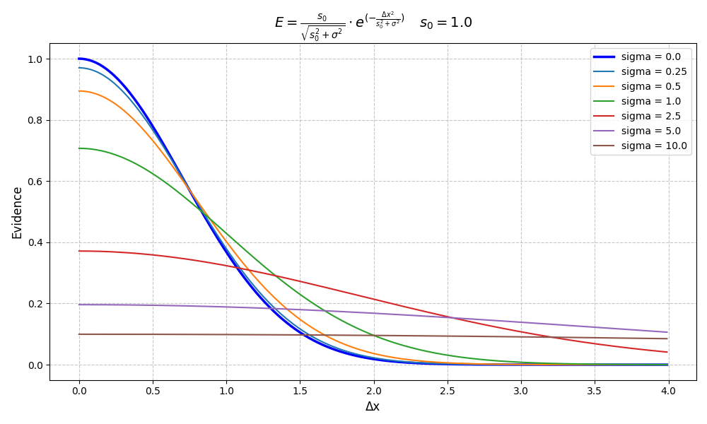
The core algorithm uses a variance-summation model. The Evidence Indicator E is defined by a Gaussian kernel multiplied by a normalization pre-factor that accounts for the relative weight of the measurement uncertainty.
Normalization Pre-factor: This term term of the equation above acts as a data-quality weight. It has two functions:
This plot demonstrates how the Likelihood Estimator adapts to varying levels of data quality while keeping the scale factor constant (s0 = 1.0).
Note: An increasing σ not only lowers the peak (Data Quality Weighting) but also broadens the distribution, meaning that at high uncertainty levels, the estimator becomes less sensitive to small changes in Δx.
A specialized version of the Uncertainty-Weighted Likelihood Estimator is used to calculate the Velocity Evidence Indicator. It evaluates the kinematic consistency of a pair by analyzing relative velocities while accounting for physical constraints and data quality.
To maintain reliability in the presence of measurement noise, the algorithm monitors the Signal-to-Noise Ratio (SNR). In cases of a Low SNR (< 3.0), the system additionally calculates the Evidence Indicator based on the projected separation. This mitigates the risk of large radial distance uncertainties distorting the kinematic assessment.
The scale factor v0 determines the tolerance of the likelihood curve. The algorithm distinguishes between two search modes:
To assist in the interpretation of the numerical results (ranging from 0.0 to 1.0), the Velocity Evidence Index is categorized into four qualitative labels:
| Evidence Index | Label | Interpretation |
|---|---|---|
| 0.7 – 1.0 | Strong | High probability of physical association (CoMov or Binary). |
| 0.3 – 0.7 | Moderate | Potential association; data supports kinematic similarity. |
| 0.1 – 0.3 | Weak | Low kinematic agreement; likely a chance alignment. |
| < 0.1 | Unlikely | Significant velocity discrepancy; association improbable. |
The Distance Evidence Indicator utilizes a specialized version of the Uncertainty-Weighted Likelihood Estimator to evaluate the spatial proximity of a stellar pair. By analyzing geometrical consistency and relative distance while accounting for physical constraints and data quality, it provides a robust measure of whether two stars are truly co-located.
To maintain reliability in the presence of measurement noise, the algorithm monitors the Signal-to-Noise Ratio (SNR). In cases of a Low SNR (< 3.0), the system additionally calculates the Evidence Indicator based on the projected separation. This mitigates the risk of large radial distance uncertainties distorting the kinematic assessment.
Depending on the selected analysis mode, the algorithm adjusts its internal scale factor (s0) and units to match the expected physical dimensions:
Similar to the kinematic assessment, the Distance Evidence Index is mapped to qualitative labels to provide a quick interpretation of spatial consistency:
| Evidence Index | Label | Interpretation |
|---|---|---|
| 0.7 – 1.0 | Strong | Excellent spatial agreement; the pair is clearly co-located. |
| 0.3 – 0.7 | Moderate | Good spatial agreement; consistent with a common origin or group. |
| 0.1 – 0.3 | Weak | Marginal spatial agreement; distance difference is significant. |
| < 0.1 | Unlikely | Significant spatial discrepancy; co-location is improbable. |
The kinematic and spatial results are synthesized into a single, unified metric. This provides a final assessment of the physical association between two stars. The total evidence is calculated using the geometric mean of the Velocity Evidence (Evelocity) and the Distance Evidence (Edistance):
The resulting index serves as the final "Confidence Score" for the pair's Co-Moving (CoMov) or Binary status:
| Total Evidence | Final Label | Physical Interpretation |
|---|---|---|
| 0.7 – 1.0 | Strong | High confidence pair; kinematic and spatial data are fully consistent. |
| 0.3 – 0.7 | Moderate | Likely association; supported by data but may have moderate uncertainties. |
| 0.1 – 0.3 | Weak | Suspicious pair; discrepancies in either motion or distance suggest a chance alignment. |
| < 0.1 | Unlikely | No physical association; the stars are very likely independent field stars. |
The table below provides a quick overview of the calculated UWLE Evidence Indicators and their parametrization:
| Condition | Mode | Type | Distance Scaling s0 | Velocity Scaling v0 | Δx | Uncertainty |
|---|---|---|---|---|---|---|
| - | Co-Moving | COMOV | 1.0 pc | 5 km/s | spatial | σspatial |
| - | Wide Binaries (3D) | WBS | 20,000 au | spatial | σspatial | |
| Sϖ < 3.0 | Wide Binaries (2D) | WBS | 20,000 au | projected | σspatial | |
| Sϖ < 3.0 | Tight Binaries (2D) | TBS | 1,000 au | projected | σprojected |
Determining the true 3D spatial separation () between two binary components from astrometric observations (such as Gaia parallaxes) involves significant measurement uncertainties. While the calculated 3D distance is typically represented as a mean value with a standard deviation , assessing whether the pair is consistent with a physically bound system benefits from a probabilistic treatment of the spatial separation uncertainty.
In observational astronomy, the projected separation on the sky plane () represents an absolute physical lower bound for the true spatial distance:
where is the unknown distance along the line of sight. Standard Gaussian models assign non-zero probabilities to values below and even to unphysical negative distances. To eliminate these physical impossibilities, the probability density function is truncated below and renormalized over the physically allowed domain .
Let the unconstrained 3D spatial separation be modeled as a normally distributed random variable , where and . The standard Gaussian cumulative distribution function is given by:
To ensure numerical stability in the extreme upper tails of the distribution, the survival function is calculated via standard normal symmetry as . The probability that the true distance lies above the physical lower bound serves as the normalization factor .
For any distance threshold , the cumulative probability conditioned on is derived as:
The probability pipeline evaluates the system against both dynamic thresholds specific to the pair's geometry and established astrophysical milestones:
Fixed thresholds that fall below the dynamic lower limits are automatically filtered out to ensure monotonically increasing evaluations.
To physically assess whether a binary star system is gravitationally bound, the Double Star Calculator utilizes the specific binding energy approach defined by Letchford et al. (2022) [11]. A binary pair is considered gravitationally bound if the total energy of the system in the center-of-mass frame is negative.
The calculated threshold serves as a physical upper integration limit within the lower-truncated normal distribution (3D Spatial Distance Probability Analysis). If the true 3D spatial separation exceeds , gravitational attraction is insufficient to maintain a bound orbit against the observed relative velocity. Evaluating the cumulative probability distribution from the projected separation up to directly yields the physical binding probability of the binary system.
By applying the reduced mass for the relative motion of two bodies, the energy balance is formulated as follows:
Substituting and simplifying the reduced mass , the condition for gravitational binding reduces to:
The critical binding distance defines the exact spatial separation at which the kinetic energy of relative motion equals the gravitational potential energy ().
The threshold serves as a physical upper integration limit within the lower-truncated normal distribution. If the true 3D spatial separation exceeds , gravitational attraction is insufficient to maintain a bound orbit against the observed relative velocity. Evaluating the cumulative probability distribution from the projected separation up to directly yields the physical binding probability of the binary system.
When a potential binary is identified, the tool evaluates the gravitational relationship:
| η < 0.5 | : Strongly bound system (deep gravity well) |
| 0.5 ≤ η < 1.0 | : Bound, but on a high-energy or highly eccentric orbit |
| η ≥ 1.0 | : Unbound; the system has reached or exceeded escape velocity |
Definition of specific energy:
Definition of Escape Velocity:
Substitution:
Final equation:
Definitions:
The Metallicity Analysis [M/H] routine is designed for the comparative analysis of the chemical composition of stellar pairs using Gaia DR3 GSP-Phot (Aeneas) data. By comparing the iron abundance ([M/H]), the algorithm assesses whether a stellar pair exhibits a consistent chemical signature—a primary indicator of a shared origin (co-natal stars). The methodology incorporates the statistical processing of asymmetric MCMC (Markov Chain Monte Carlo) confidence intervals, the calculation of combined uncertainties in quadrature, and a quality weighting based on photometric transit integrity.
1. Deriving Standard Deviation from MCMC Percentiles
Gaia GSP-Phot provides metallicity as the median of an MCMC sample, along with the 16th (lower) and 84th (upper) percentiles. To convert these asymmetric confidence intervals into a symmetric standard deviation suitable for error propagation, the routine calculates the arithmetic mean of the absolute deviations:
2. Statistical Significance (Z-Score)
To evaluate the chemical consistency between both stars, a Z-Score is calculated. While measurement errors are assumed to be independent and normally distributed, the statistical uncertainties from Gaia DR3 often underestimate systematic effects like parameter degeneracies. To ensure a robust comparison, a systematic uncertainty floor (σsys = 0.21 dex) is incorporated into the Gaussian error propagation. This floor is based on the Median Absolute Deviation (MedAD) observed in validation studies (cf. R.Andrae, M.Fouesneau et al. (2023) [7]), comparing Gaia GSP-Phot with high-resolution spectroscopy.
The resulting Z-Score represents the number of standard deviations separating the two measurements:
3. Photometric Metallicity Confidence Factor (PMCF)
To evaluate the reliability of the spectroscopic data, a proprietary Photometric Metallicity Confidence Factor (PMCF) is calculated. This factor accounts for contaminated and blended transits in the BP/RP spectra. Contaminated transits are fully weighted, while blended transits are weighted at 50% (0.5) to reflect their partial impact on spectral purity:
Note: A low PMCF (< 0.80) indicates poor data quality, suggesting that even low Z-scores should be interpreted with caution.
| Z-Score Range | Scientific Interpretation |
|---|---|
| Z ≈ 0 | Chemically consistent. High probability of a shared origin. |
| Z < 3 | Marginally consistent within the 3σ threshold. |
| Z ≥ 5 | Highly significant difference. Physical association is statistically excluded. |
If historical measurements of the separation and position angle are provided, the Double Star Calculator performs a trend analysis on the astrometric residuals of the double star. It quantifies the deviations of the historical measurements from a kinematic motion predicted reference model based on Gaia proper motion data.
The core of the residual analysis is the computation of a trend analysis (sequential polynomial fit) with three different competing regression models. For each model the Root Mean Square (RMS) is calculated and the Durbin-Watson Test are performed:
To mitigate numerical instabilities and loss of precision during higher-order polynomial fitting, the observational epochs are centered around a user-defined reference epoch (T0 = 2000.0). For each epoch ti, the relative epoch Δti is computed as:
The raw residuals are computed directly from the difference between historical measurements and the Gaia reference model. For angular separations (ρ), a linear difference is used, while Position Angles (PA) require a wrap-around correction to account for the 360° periodicity:
The global metrics for the raw residual dataset consisting of N measurements are defined as follows. The implementation in Python is based on NumPy (np):
PYTHON: mae = np.mean(np.abs(residuals))PYTHON: bias = np.mean(residuals)PYTHON: rmse = np.sqrt(np.mean(residuals**2))Calculated using Delta Degrees of Freedom (ddof = 1) to provide an unbiased estimator for smaller sample sizes:
PYTHON: stdev = np.std(residuals, ddof=1)The Durbin-Watson score (DW) checks for sequential first-order autocorrelation between successive data records. It is computed both for the raw residuals and the post-fit residuals of the regression models using the following equation, Where εi represents the evaluated series (either raw residuals or post-fit residuals):
PYTHON: dw = durbin_watson(residuals)The application fits three competing polynomial orders to the raw residuals (Ri) over the relative epochs (Δti). The execution uses algebraic matrix inversion via least squares minimization. For each model, the Root Mean Square (RMS) of the remaining post-fit residuals is computed.
Models a systematic, static baseline shift by applying the arithmetic mean:
PYTHON:
a_const   = np.mean(residuals)
fit_const = np.full_like(residuals, a_const)
rms_const = np.sqrt(np.mean((residuals - fit_const)**2))
dw_const  = durbin_watson(residuals - fit_const)
Models a constant velocity drift discrepancy using a standard linear slope:
The coefficients b (velocity drift) and a (intercept) are obtained by minimizing the squared errors over the array. Implemented in Python as:
PYTHON:
coeff_linear = np.polyfit(t_rel, residuals, 1)
b_lin, a_lin = coeff_linear
fit_linear   = np.polyval(coeff_linear, t_rel)
rms_linear   = np.sqrt(np.mean((residuals - fit_linear)**2))
dw_linear    = durbin_watson(residuals - fit_linear)
Captures a constant acceleration component to trace non-linear orbital trends:
Where $c$ represents the acceleration coefficient. Implemented in Python as:
PYTHON:
coeff_quad             = np.polyfit(t_rel, residuals, 2)
c_quad, b_quad, a_quad = coeff_quad
fit_quad               = np.polyval(coeff_quad, t_rel)
rms_quad               = np.sqrt(np.mean((residuals - fit_quad)**2))
dw_quad                = durbin_watson(residuals - fit_quad)
For each specific model fit, the remaining scatter (RMS) of the post-fit residuals is mathematically defined via:
This chapter describes auxiliary functions used in the analysis of stellar kinematics and physical association. These functions support the main astrometric routines and provide derived quantities and comparison metrics.
This function converts the stellar parallax into distance, expressed in parsecs and light-years, including the propagation of the parallax uncertainty.
The calculation follows the standard astronomical relation between parallax and distance and assumes Gaussian error propagation.
where is the parallax in milliarcseconds (mas).
The uncertainty is derived using standard Gaussian error propagation.
with the conversion constant .
Calculates a conservative lower bound of the projected physical separation in parsec between two stars by evaluating the projected separation at the average distance davg of both components.
where θ is the angular separation and σθ the uncertainty of the angular separation.
Note: For pairs with very small angular separations (≤ 100″), the geometric projection term tan(θ) approaches zero. Consequently, the impact of the distance uncertainty (σd) on the physical separation error is minor and has been intentionally omitted.
This function calculates the absolute magnitude of a star from its apparent Gaia G-band mean magnitude mG and its distance in parsecs dpc. This value is corrected for stellar extinction AG (G-band) and indicated, whenever the corresponding data is available in the Gaia database.
Computes the absolute angular difference between two proper motion position angles, normalized to the range 0°–180°.
Uncertainty:
Computes the absolute difference in total proper motion between two stars.
Uncertainty:
The following auxiliary functions compute absolute differences in tangential, radial, and total space velocity using identical mathematical formulations.
Generic Equation:
Uncertainty:
This formulation applies to:
The magnitude of the vectorial difference between the stars' 3D velocity vectors. Unlike the scalar version, this value accounts for the stars' actual directions of motion. It represents the total relative speed between the two components. The following function computes the 3D velocity difference.
Velocity Component Calculation:
Error Propagation of Individual Components:
Total Velocity Difference (Δvrel):
Final Error Propagation (σΔv):
where .
Nomenclature & Constants
| Symbol | Description | Value / Unit / Definition |
|---|---|---|
| au to km/s conversion factor | 4.74057 | |
| Radial velocity weighting factor | 1.0 (enabled) or 0.0 (disabled) | |
| Parallax | mas | |
| Proper Motion in Right Ascension (μα · cos δ) | mas/yr | |
| Proper Motion in Declination | mas/yr | |
| Standard uncertainty (Sigma) | Associated error of a variable | |
| Tangential velocity component | km/s | |
| Radial velocity component | km/s | |
| Relative Velocity (3D) Difference | km/s (Vectorial Difference) |
Estimates the stellar spectral class and temperature using the Gaia BP–RP color index based on empirical color boundaries. The temperatures are derived from data provided by the University of Northern Iowa [8].
    Spectral class |  BP-RP  Color-Index    |  Temperature
    ---------------|--------------------------------------
    O:             |         bp_rp < -0,1   |    50000
    B:             | -0,1  ≤ bp_rp ≤  0,3   |    15000
    A:             |  0,3  < bp_rp ≤  0,5   |     8750
    F:             |  0,5  < bp_rp ≤  0,72  |     6700
    G:             |  0,72 < bp_rp ≤  1,14  |     5800
    K:             |  1,14 < bp_rp ≤  1,8   |     4800
    M:             |         bp_rp >  1,8   |     3300
    ------------------------------------------------------
The function returns one of the spectral classes: O, B, A, F, G, K, M.
This is an approximate classification intended for statistical and comparative analysis.
This chapter describes the estimation of stellar luminosity and mass for main-sequence stars based on their absolute magnitude and spectral type. The implemented method follows the segmented mass–luminosity relations presented by Eker et al. (2018) [9], adapted here to broad spectral-type intervals for practical application. The luminosity is derived from the absolute magnitude relative to the Sun, including a bolometric correction. The stellar mass is subsequently computed by inverting the logarithmic mass–luminosity relation.
Luminosity:
The stellar luminosity expressed in units of the solar luminosity where is the absolute Gaia G-band magnitude of the star and is the solar absolute bolometric magnitude, adopted here as . A bolometric correction factor () according to Pecaut and Mamajek (2013), updated via the online dwarf star properties compilation (Mamajek 2022) [10] is applied based on the estimated spectral type to determine the bolometric magnitude:
    "O5V" => -3.76
    "B5V" => -1.34
    "A5V" =>  0.00
    "F5V" => -0.02
    "G5V" => -0.105
    "K5V" => -0.63
    "M5V" => -3.11
Given an uncertainty in the absolute G-band magnitude, lower and upper luminosity limits are computed as:
Mass–Luminosity Relation and Mass Estimation:
Eker et al. (2018) describe the mass–luminosity relation for main-sequence stars as a segmented power law based on the stellar mass (expressed in solar masses, ):
Here, is the slope and the intercept of the logarithmic relation, both depending on the stellar mass regime. For mass estimation, the relation is inverted to yield:
    "O" => { α: 3.96, C:  0.00 }, # High Mass
    "B" => { α: 3.96, C:  0.00 }, # High Mass
    "A" => { α: 4.67, C: -0.15 }, # Intermediate Mass
    "F" => { α: 4.67, C: -0.15 }, # Intermediate Mass
    "G" => { α: 5.56, C: -0.03 }, # Low Mass
    "K" => { α: 4.20, C: -0.20 }, # Ultra-Low Mass
    "M" => { α: 2.27, C:  0.60 }  # Ultra-Low Mass
The positions of both components are plotted in a simplified Hertzsprung–Russell diagram (HRD). The positions are derived from their calculated stellar luminosities, expressed in solar luminosities and converted to logarithmic scale, and from their effective temperatures (Teff) as provided by Gaia (plotted as solid circles). The effective temperatures are taken from the Gaia GSP-Phot Aeneas solution based on BP/RP spectra (teff_gspphot) and are likewise converted to logarithmic scale. In case the effective temperature is not available, the temperature is estimated from the color index (bp_rp) measured by Gaia (plotted as open circles). Upper and lower bounds of both luminosity and effective temperature are propagated into logarithmic space to derive symmetric uncertainties for the HRD coordinates.
In addition to the stellar positions, the HRD includes schematic regions indicating the approximate locations of the main sequence, giant stars, supergiants, and white dwarfs. These regions are intended for qualitative orientation within the HR diagram and are based on standard tabulated relations between spectral type and effective temperature, such as those provided by the University of Northern Iowa [8].
The Double Star Calculator – Orbital Elements generates orbit diagrams and a corresponding ephemeris table showing the separation and position angle of a double star based on its orbital elements. This section documents the mathematical functions used to compute the apparent visual positions of a binary star system.
The Mean Anomaly represents the time elapsed since the last periastron passage, scaled by the orbital period and expressed as an angular measure wrapped into the range 0 to 2π.
Kepler's equation relates the eccentric anomaly E to the mean anomaly M, where the mean anomaly serves as the time-dependent parameter.e is the orbital eccentricity:
Kepler's equation is a transcendental equation and therefore cannot be solved analytically. It is solved numerically using the Newton-Raphson method. The initial guess is selected dynamically. For low-eccentricity orbits (e < 0.8), the iteration starts with E = M. For highly eccentric orbits (e ≥ 0.8), the initial guess is set to π to improve numerical convergence. The estimate of E is then iteratively refined using:
The iteration terminates once the residual error falls below the specified tolerance (10-9). A strict safety limit of 100 iterations prevents infinite loops. This is particularly important for highly eccentric binary systems (e ≈ 0.98), where convergence may become significantly slower near periastron.
Once the Eccentric Anomaly is successfully resolved, the physical orbital track is evaluated using three sequential mathematical relations:
atan2) to determine the angle accurately across all four quadrants:
To display the orbit as observed on the sky, the true orbital coordinates are projected onto the plane of the sky using the three Campbell elements: the position angle of the ascending node, the argument of periastron, and the orbital inclination. This transformation produces the apparent orbital ellipse:
The Double Star Calculator – Orbit Determination (DSC-OD) determines the visual orbital elements of a binary star system from a time series of relative astrometric measurements. The observational dataset consists of discrete epochs , angular separations (in arcseconds), and position angles (in degrees, measured east of north):
From these visual observations on the celestial sphere—representing the apparent projection of a true two-body Keplerian orbit—the module fits the seven classical orbital elements (the Campbell parameters):
Due to the non-linear relationship between the orbital elements and the apparent visual positions (, ), finding the global minimum of the objective function requires suitable initial parameter estimates. To ensure robust convergence of the non-linear solver, the algorithm provides three distinct initialisation strategies:
The Simple Initial Guess Estimator provides a robust starting point directly derived from the observational time domain and projected astrometric geometry for the seven orbital Campbell elements. The method is intentionally heuristic and is designed to provide stable initial values for subsequent non-linear optimization rather than physically accurate orbital elements.
The orbital period estimate is evaluated using the continuous, unwrapped total angular rotation over the observation time span . If the observations cover approximately three-quarters of a full revolution or more (), the time span itself serves as the period estimate; otherwise, it is conservatively scaled to twice the covered time span:
The semi-major axis is estimated using the arithmetic mean of the maximum and minimum observed angular separations ( and ):
The longitude of the ascending node is aligned with the observed position angle corresponding to the epoch of maximum angular separation :
The argument of periastron is initialized to zero:
The epoch of periastron passage is estimated by starting at the earliest observation epoch and shifting forward by 20% of the estimated orbital period :
Inclination and eccentricity are assigned fixed default values. The inclination is initialized to its theoretical expectation value for isotropically oriented orbital planes in three-dimensional space ():
The Thiele-Innes Initial Guess Estimator simplifies orbit determination by decoupling the seven orbital parameters into two distinct sets: three non-linear orbital shape and timing parameters (), and four linear spatial orientation constants known as the Thiele-Innes constants (). By scanning a candidate grid over the non-linear parameter space, the optimal spatial orientation constants are determined at each node via linear least-squares. If fewer than four observations are available, or if the grid search fails to yield a physically valid solution, the algorithm automatically falls back to the Simple Initial Guess Method.
By evaluating a candidate grid of , the spatial orientation parameters are solved instantly via linear least-squares at each node. The parameter set yielding the lowest residual error is selected and analytically transformed into the geometric Campbell orbital elements ().
Observed polar astrometric coordinates (angular separation and position angle ) are mapped into standard relative Cartesian coordinates on the celestial tangent plane, where represents Right Ascension offset (East) and represents Declination offset (North):
A candidate grid evaluates combinations over the bounded domain of non-linear parameters:
For each candidate grid node , the mean anomaly is converted to eccentric anomaly via Kepler's equation (). Normalized coordinates in the true orbital plane are computed as:
The projected positions follow the linear relations and . This forms an overdetermined linear system :
The system is solved via linear least squares:
The grid combination yielding the minimum sum of squared Cartesian residuals:
is selected as the global initial guess.
The optimal Thiele-Innes constants are analytically inverted into geometric Campbell parameters (). First, two fundamental algebraic invariants are evaluated:
Solving the characteristic quadratic equation—including numerical safeguards against floating-point underflow—yields the semi-major axis and inclination :
The longitude of the ascending node and argument of periastron are decoupled via the van den Bos (1926) sum and difference angle equations:
Solving for and yields:
The orbit determination of visual binary stars represents a non-linear inverse problem in astrometry. Given a set of N observational epochs tk, angular separations ρk (in arcseconds), and position angles θk (in degrees, measured from North through East), the goal is to determine the seven canonical Campbell orbital elements:
The bounds for the calculation of the orbital elements are defined as follows:
Astrometric measurements of visual binary stars originate from diverse observational techniques spanning over two centuries of historical and modern astronomy. Consequently, observational uncertainties range from subjective visual estimates to sub-milliarcsecond space-based measurements. To perform a statistically rigorous weighted orbit determination, each measurement pair, comprising angular separation () and position angle (), must be assigned individual, physically realistic 1- standard uncertainties ( and ).
The preprocessing pipeline parses raw observation catalogs compliant with the United States Naval Observatory (USNO) Washington Double Star (WDS) specification. It executes a deterministic multi-tier error allocation model. This model imports published formal catalog errors, applies category-specific systematic error floors in quadrature, imputes technique-dependent default values for unquantified historical data, and enforces strict defensive bounds against unphysical or zero-uncertainty values.
Raw observation data lines adhere to the post-May/June 2012 expanded fixed-width USNO WDS observation catalog format. Data parsing is performed by extracting specific column ranges via fixed-width slicing:
| Quantity | Symbol | WDS Columns | Format | Unit | Description |
|---|---|---|---|---|---|
| Observation Date | 008–017 | f10.5 |
Decimal Years | Epoch of observation | |
| Position Angle | 020–026 | f7.3 |
Degrees (°) | Observed position angle (0° to 360°) | |
| PA Formal Error | 028–033 | f6.3 |
Degrees (°) | Published formal uncertainty in | |
| Separation | 036–044 | f9.5 |
Arcseconds (″) | Observed angular separation | |
| Separation Error | 047–053 | f7.5 |
Arcseconds (″) | Published formal uncertainty in | |
| Technique Code | tech |
112–113 | a2 |
Text Code | Two-character observational technique identifier |
The primary character of the two-letter technique code (column 112) maps the measurement into one of seven broad astronomical technique categories (). If no technique code is supplied, or an unmapped character is encountered, the record is assigned to the default fall-back category (DEF).
| Category Code | WDS Technique Prefixes | Observational Methodology | Default Uncertainty (, ) | Systematic Floor (, ) |
|---|---|---|---|---|
VIS |
M, V, D, T | Visual micrometrical, meridian circle, heliometer, transit circle | 0.100″, 1.000° | 0.050″, 0.500° |
PHO |
P | Photographic plates / analog emulsions | 0.060″, 0.600° | 0.030″, 0.300° |
CCD |
C, E, A | Ground-based CCD, CMOS, electron multiplication, lucky imaging | 0.035″, 0.400° | 0.010″, 0.200° |
SPE |
S | Speckle interferometry | 0.004″, 0.200° | 0.002″, 0.100° |
INT |
I, J, K | Long-baseline optical, infrared, radio, or aperture-masking interferometry | 0.002″, 0.100° | 0.0005″, 0.050° |
SPA |
H | Space-based astrometry (e.g., Hipparcos, Tycho-2, Gaia, HST) | 0.001″, 0.050° | 0.0005″, 0.050° |
SPC |
X, Z, O | Spectroscopic binaries, eclipse minimum timing, occultation timing | 0.050″, 0.500° | 0.020″, 0.300° |
DEF |
Unmapped / Blank | Global fall-back for unspecified observational methods | 0.100″, 1.000° | 0.010″, 0.200° |
The assignment of final effective uncertainties ( and ) follows a deterministic decision matrix designed to prevent over-weighting due to underestimated internal errors published in catalogs.
When a published formal error value is present and strictly positive (), it is combined in quadrature with the corresponding category-specific systematic error floor :
This quadrature addition ensures that even if an observer reports extremely small formal measurement uncertainties, the weight of the observation within the orbit fitting routine remains bounded by the physical limits of the underlying technique (e.g., atmospheric seeing limits, optical diffraction limits, or detector pixel scales).
Historical catalogs frequently omit error estimates or use placeholder tokens. To ensure numerical stability and prevent mathematical singularities during matrix inversions, exception handling is governed by the following rules:
0.0 or 0.000 does not represent zero variance, but rather a catalog placeholder indicating unquantified precision. Evaluating would yield an infinite weight, forcing the orbit optimizer to pass exactly through that data point. The system intercepts all non-positive entries (), rejects them as valid catalog uncertainties, and falls back to the technique category defaults .
The effective uncertainty arrays ( and ) generated during preprocessing form the statistical foundation for the subsequent orbit determination routines. By supplying strict, non-zero standard errors for every observational pair, the pipeline enables a fully weighted -minimization.
For a given epoch tk and parameter vector p = [P, a, i, Ω, T, e, ω]T, the theoretical position of the secondary star relative to the primary is evaluated through Kepler's laws and Campbell projection equations.
First, the mean anomaly Mk is computed from the mean motion n = 2π / P:
The eccentric anomaly Ek is obtained by solving Kepler's transcendental equation:
The true anomaly νk and the orbital radius vector rk (in the true orbital plane) are derived using standard half-angle relations:
The true orbit is projected onto the tangential sky plane using the argument of latitude uk = νk + ω. According to standard astronomical conventions, x represents the offset toward East (Δα cos(δ)) and y represents the offset toward North (Δδ):
The apparent model separation ρmod,k and position angle θmod,k are extracted via:
The normalized cartesian residuals are computed between the observed and model-predicted relative positions of a visual binary. The observed polar measurements (separation and position angle) and their uncertainties are transformed into Cartesian East and North coordinates using rigorous error propagation. The resulting weighted residual vector is intended for least-squares optimization of the orbital elements.
Observations are mapped onto orthogonal Tangential Sky Coordinates (xobs, yobs):
Applying Gaussian error propagation to this coordinate transformation yields cartesian variance estimates sx,k2 and sy,k2:
The normalized residual vector r(p) ∈ ℝ2N is assembled by concatenating weighted orthogonal components:
The central orbit fitting routine employs an adaptive strategy balancing global exploration and local refinement.
Once a promising starting guess is established (via DE, Thiele-Innes grid search, or catalog values), a local Trust-Region Reflective (TRF) algorithm refines the parameters. TRF solves the bounded non-linear least-squares problem:
The local curvature of the cost function is derived from the 2N × 7 Jacobian matrix J, where Jm,j = ∂rm / ∂pj. To handle potential rank deficiency or strong parameter correlations robustly, the covariance matrix C is evaluated via Singular Value Decomposition (SVD) pseudo-inversion:
If unweighted fitting is performed (σρ = None), the covariance matrix is scaled by χred2. Formal 1σ standard errors for each orbital parameter pj are given by:
Additionally, the condition number κ(JTJ) = σmax / σmin is recorded to diagnose ill-conditioned systems.
The Optimization Summary provides quantitative measures describing the quality, robustness, and statistical consistency of the orbit determination based on the supplied observations and measurement uncertainties. It should be interpreted as a whole. Individual metrics are most meaningful when considered together, particularly in relation to the number of observations, the orbital phase coverage, and the assumed measurement uncertainties.
Number of observations used in the orbit determination. Each observation consists of a measured separation () and position angle (), contributing two residuals ( and ) to the fit.
Time interval covered by the observations, given by the minimum and maximum observation epochs. A larger time span generally improves orbit determination, especially for long-period systems, as it increases orbital phase coverage.
Fraction of the orbital period covered by the observations, where is the fitted orbital period. Values close to or exceeding one full period generally provide stronger constraints on the orbital elements, while smaller values indicate limited phase coverage and potential parameter degeneracies.
The total chi-squared value of the fit, defined as the sum of squared, uncertainty-weighted residuals, where (, ) are the Cartesian coordinates derived from the separation and position angle, and , are the corresponding propagated uncertainties. χ² measures the overall disagreement between the model and the observations. In this implementation, χ² is calculated from normalized Cartesian residuals.
Number of independent residuals available to evaluate the fit after accounting for the fitted model parameters. For observations and seven fitted orbital elements (, , , , , , ), the degrees of freedom are given by the equation below. A positive and sufficiently large number of degrees of freedom is required for a meaningful statistical interpretation of χ² and reduced χ².
The reduced χ² indicates how well the orbital model matches the observations relative to the assumed measurement uncertainties.
Indicates whether the numerical optimization converged (Converged or Not converged).
The condition number () of the covariance matrix. Quantifies the numerical stability of the inversion and parameter correlations during the fit. It serves as a scalar measure for the numerical stability of the linear inversion and the degree of parameter correlation.
Root-mean-square (RMS) residual of the separation (ρ), calculated from the differences between observed and modeled separations. This value quantifies the typical deviation of the observations from the model.
While standard RMS residuals treat all observation epochs equally, the Weighted Root Mean Square (WRMS) residuals account for varying measurement uncertainties. Each residual is weighted by the inverse square of its individual observational error (σ), ensuring that high-precision measurements (e.g., modern interferometry or space-based astrometry) have a stronger influence on the overall quality assessment than historical visual observations with higher uncertainties.
The weighting factor for an observation epoch i is calculated as:
The WRMS residuals for the separation () and position angle () are defined as:
|
Weighted RMS Separation (arcsec): |
Weighted RMS Position Angle (deg): |
Where and represent the individual O−C residuals at epoch i. If individual observational errors are omitted, the calculation falls back to standard unweighted RMS statistics.
Root-mean-square (RMS) residual of the position angle (), calculated from the differences between observed and modeled angles. The RMS position angle reflects the typical angular discrepancy between the model and the observations.
Note: Angular differences () are phase-wrapped to the range [−180°, 180°] prior to squaring to handle the 360° boundary discontinuity correctly.
The root-mean-square (RMS) of position angle residuals projected into spatial arc length by multiplying the angular offset (in radians) by the observed separation .
Maximum absolute residual of the separation (). This value highlights the largest individual deviation between an observed separation and the corresponding model prediction.
Maximum absolute residual of the position angle (), dynamically wrapped to ensure correct boundary evaluation. This value highlights the largest individual angular deviation.
This subsection lists the formal 1- standard uncertainties for the 7 fitted orbital elements. When a valid covariance matrix is available, uncertainties are evaluated from the diagonal elements:
If a diagonal element is non-positive () or the covariance matrix cannot be computed, the uncertainty for that parameter is set to NaN. Angular uncertainties (, , ) are automatically converted from radians to degrees.
| Key | Parameter | Symbol | Description | Units |
|---|---|---|---|---|
P |
Period | Orbital period | yr | |
a |
Semi-major axis | Semi-major axis | arcsec | |
i |
Inclination | Inclination angle | degrees | |
Omega |
Node | Longitude of the ascending node | degrees | |
T |
Periastron passage | Epoch of periastron passage | yr | |
e |
Eccentricity | Orbital eccentricity | -- | |
omega |
Arg. of periastron | Argument of periastron | degrees |
Note: For highly non-linear fitting problems or large condition numbers, these asymptotic 1- errors represent a lower bound on the true uncertainties (Cramér-Rao bound).
To provide an automated and objective assessment of the calculated orbital elements, the software computes an Estimated Orbit Grade on a numerical scale from 1 (Definitive) to 5 (Indeterminate). This classification scheme is conceptually aligned with the grading system used in the USNO Sixth Catalog of Orbits of Visual Binary Stars, combining observational completeness, parameter stability, and numerical quality into a single metric.
The grading algorithm evaluates the fit results in a hierarchical decision tree based on five primary key performance indicators:
Grades are assigned sequentially from Grade 1 down to Grade 5. The first set of conditions that is fully satisfied determines the final grade. Unless explicitly stated otherwise (e.g., using an explicit OR or ANY operator), all conditions listed for a particular grade must be satisfied simultaneously (logical AND).
| Grade | Rating Label | Evaluation Criteria / Decision Rules | Description |
|---|---|---|---|
| 1 | Definitive |
|
Full or near-full orbital coverage; extremely well-constrained parameters and low residuals. |
| 2 | Good |
|
Well-observed arc with reliable parameters, well-managed residuals, and high confidence. |
| 3 | Reliable |
|
Partial orbit coverage; key features or periastron passage captured. |
| 4 | Preliminary |
|
Short observational arc; period and major semi-axis remain subject to revision. |
| 5 | Indeterminate |
Triggered if ANY of the following apply:
|
Extremely short arc, severe parameter degeneracy, excessive observational scatter, or numerical instability. |
Automated health flags and diagnostic messages evaluated during orbit optimization to highlight numerical instabilities, data coverage limitations, or statistical anomalies:
NaN values).
opt_message).
Version 1.0 : https://doi.org/10.5281/zenodo.19160070
Version 1.1 : https://doi.org/10.5281/zenodo.19474677
Version 1.2 : https://doi.org/10.5281/zenodo.22309756
The Double Star Calculator makes use of data from the European Space Agency (ESA) mission Gaia, processed by the Gaia Data Processing and Analysis Consortium (DPAC). Funding for the DPAC has been provided by national institutions, in particular the institutions participating in the Gaia Multilateral Agreement. Additionally, it incorporates data from the Washington Double Star Catalog, maintained at the U.S. Naval Observatory, makes use of the Aladin Sky Atlas developed at CDS, Strasbourg Observatory, France, and makes use of the SIMBAD database, operated at CDS, Strasbourg, France.
[1] Wichmann, H. (2026), Double Star Calculator, https://www.stella-vega.de/ds/
[2] Wichmann, H. (2026), Double Star Calculator - Technical Documentation, https://stella-vega.de/ds/ds_documentation.html
[3] Harshaw, Richard W. (2016), CCD Measurements of 141 Proper Motion Stars: The Autumn 2015 Observing Program at the Brilliant Sky Observatory, Part 3 (Journal of Double Star Observations, Vol. 12 No. 4 April 22, page 394), http://www.jdso.org/volume12/number4/Harshaw_394_399.pdf
[4] Tian, Hai-Jun; El-Badry, Kareem; Rix, Hans-Walter; Gould, Andrew (2020), The Separation Distribution of Ultrawide Binaries across Galactic Populations (The Astrophysical Journal Supplement Series, 246:4), https://ui.adsabs.harvard.edu/abs/2020ApJS..246....4T/abstract
[5] El-Badry, Kareem; Rix, Hans-Walter; Heintz, Tyler M. (2021), A million binaries from Gaia eDR3: sample selection and validation of Gaia parallax uncertainties (Monthly Notices of the Royal Astronomical Society, Volume 506, Issue 2, Pages 2269–2295), https://ui.adsabs.harvard.edu/abs/2021MNRAS.506.2269E/abstract
[6] J. A. Correa-Otto and R. A. Gil-Hutton (2017), Galactic perturbations on the population of wide binary stars with exoplanets (A&A, Volume 608, December 2017), https://www.aanda.org/articles/aa/abs/2017/12/aa31229-17/aa31229-17.html
[7] R. Andrae, M. Fouesneau, R. Sordo, et al. (2023), Gaia Data Release 3, Analysis of the Gaia BP/RP spectra using the General Stellar Parameterizer from Photometry (A&A, Volume 674, June 2023), https://www.aanda.org/articles/aa/full_html/2023/06/aa43462-22/aa43462-22.html
[8] University of Northern Iowa, Spectral type characteristics, https://sites.uni.edu/morgans/astro/course/Notes/section2/spectraltemps.html
[9] Eker, Z.; Bakış, V.; Bilir, S.; et al. (2018), Interrelated main-sequence mass–luminosity, mass–radius, and mass–effective temperature relations, (Monthly Notices of the Royal Astronomical Society, Volume 479, Issue 4, Pages 5491–5511), https://ui.adsabs.harvard.edu/abs/2018MNRAS.479.5491E/abstract
[10] Pecaut, M. J.; Mamajek, E. E. (2013), Intrinsic Colors, Temperatures, and Bolometric Corrections of Pre-main-sequence Stars, (The Astrophysical Journal Supplement, Volume 208, Issue 1, article id. 9), https://ui.adsabs.harvard.edu/abs/2013ApJS..208....9P/abstract, updated via the online compilation: Mamajek, E. E., 2022, A Modern Mean Dwarf Stellar Color and Effective Temperature Sequence, Version 2022.04.16, https://www.pas.rochester.edu/~emamajek/EEM_dwarf_UBVIJHK_colors_Teff.txt
[11] Roderick R. Letchford, Graeme L. White, Carolyn J. Brown (2022), Orbital Elements of visual binary stars with very short arcs: With application to double stars from the 1829 southern double star catalog of James Dunlop, (Astronomical Notes, Volume 343, Issue3), https://onlinelibrary.wiley.com/doi/10.1002/asna.20210113
www.stella-vega.de